

Key Takeaways
- Check permit and code requirements with your local municipality prior to beginning as NJ projects typically require zoning and building permits and must adhere to the UCC and NEC.
- Determine load requirements. Will you potentially need EV charging or HVAC? Feeders, subpanel, and branch circuits can be sized using NEC ampacity rules and voltage drop calculations to keep drop below 3%.
- Pick up an appropriately rated subpanel with its own neutral and ground bars. Make feeder ampacity the same as the panel rating. Allow room for subsequent circuits.
- Follow phased installation steps: trenching and conduit, pulling conductors, mounting the subpanel, terminating circuits, and scheduling inspections at trench, rough, and final stages.
- Ground and bond properly by driving grounding electroderods, connecting with properly sized copper conductors, and isolating neutral and ground in the detached garage subpanel.
- Stay away from mistakes like mixing neutral and ground, not burying low-voltage cable or conduit, not sealing cable to prevent water intrusion, and missing labels or inspections for safety and approval holdups.
How to wire a detached garage in New Jersey details necessary procedures, permits, and safety precautions to ensure your electrical project is handled properly. It goes through service type, meter and panel placement, grounding, conduit runs, circuit sizing, and GFCI protection under NJ code and NEC. As a homeowner, you typically need a permit and inspection from local authorities. The meat provides a short and clear step by step plan, common mistakes, and guides for getting a licensed electrician.
Regulatory Guidelines
Regulations provide the context for when and how you’re allowed to wire a detached garage in New Jersey. Here’s what you need to know about permit triggers, zoning versus building approvals, municipal variations, and the codes that govern electrical wiring, grounding, and inspections.
Permit Requirements
| Permit type | When required | Typical documents needed |
|---|---|---|
| Zoning permit | New garages, expansions, or changes of use; applies to setbacks, lot coverage and floor area limits | Site plan, property survey, application form, fee |
| Building (UCC) permit | Structural work, utilities, and any project over common thresholds (see note) | Construction plans, electrical drawings, load calculations, contractor info |
| Electrical permit | All electrical work beyond minor repairs; required for feeders, panels, and new circuits | Single-line diagram, panel schedule, permit application, electrician license |
Garages greater than 200 square meters? Metric: 200 square feet equals about 18.6 square meters. Projects over approximately 18.6 square meters or any garage that incorporates utilities generally require additional scrutiny and permits. Many municipalities follow the common threshold: any garage over 200 square feet or that installs plumbing or HVAC needs both zoning and building permits.
File applications with zoning and building departments as dictated by local ordinance. These are separate processes. Zoning verifies lot coverage, setbacks, and if floor area is greater than permitted. For example, this can be 20 percent of the dwelling’s gross floor area or 600 square feet, whichever is greater. Building permits are governed by New Jersey UCC, which is based on the 2021 IRC/IBC, NJ Edition, and has no local amendments. Plan for permit fees and review timelines to differ by township. Inquire early at both municipal and county offices.
Code Standards
Adhere to the present National Electrical Code for wiring means, grounding, and circuit protection. Anywhere there’s power in the garage, employ GFCI protection, covering 125 V and 250 V receptacles as well, NEC 210 and related sections, with no exceptions for height or accessibility. NEC 210.52(G) states to provide a receptacle in every vehicle bay. For detached garages or garages with heavy 240 V equipment, anticipate a dedicated subpanel fed from the main service. This isolates those loads and streamlines overcurrent protection.
Size conductors and feeders NEC ampacity tables and the connected load calculated. For underground feeders, adhere to burial depths and conduit rules. Follow local utility locates and NEC requirements for cable type and minimum cover. If there is habitable space above the garage, apply 5/8-inch Type X gypsum board on the ceiling in accordance with code requirements for fire resistance.
Inspection Protocols
Plan inspections at trenching, rough wiring, and final so work is validated incrementally. They will inspect grounding electrode systems, bonding of metal parts, proper conductor sizing, and panel labeling. Full terminations, grounded connections, and proper labeling are required before final inspection to avoid failures. Be sure to respond quickly to any correction notices to prevent project delays and extra fees.
Capacity Assessment
Capacity assessment here means determining whether the detached garage and its users, equipment, and future needs can be served safely by an electrical supply. Start by noting the site context: distance from the main service, intended uses, and who will operate equipment. This is a technical load study combined with a practical review of resources and constraints.
Load Calculations
List every planned load with wattage: fixed lighting (e.g., 10 to 20 W LED per fixture), general receptacles (allocate 180 VA per duplex per NEC-style method), motors (nameplate watts), electric heaters (watts), compressors (starting and running watts), EV chargers (typically 7,200 to 11,500 W for Level 2), and specialty tools (welders, saws). Use a table to cluster these.
| Component | Quantity | Unit Load (W) | Total Load (W) |
|---|---|---|---|
| LED lighting | 8 | 15 | 120 |
| General outlets (design) | 6 | 180 | 1,080 |
| Garage door opener | 1 | 500 | 500 |
| Air compressor | 1 | 2,000 | 2,000 |
| EV charger (optional) | 1 | 7,200 | 7,200 |
| Heater (space) | 1 | 3,000 | 3,000 |
Apply the 80% rule for continuous loads: size circuits so continuous loads do not exceed 80% of the breaker rating. For instance, 6,000 W continuous at 240 V would be 25 A continuous, so select a 30 A or larger circuit and size feeder to meet the 80% criteria. Apply NEC-style rules of thumb to convert total wattage to feeder amperage by dividing total wattage by 240 V, then choose a feeder that has at least that many amps, plus some room for growth. Always allocate dedicated circuits for high-power items. A welder, pump, or EV charger must have its own branch circuit sized to its full load plus starting current.
Subpanel Selection
Select a subpanel rated to accommodate calculated feeder amperage. For most garages, a 60 A subpanel addresses the basics. A 100 A panel is a frequent choice when anticipating EV charging or HVAC. Choose a panel with room for existing branch circuits and 25 to 30 percent spare spaces for growth. Verify the panel design has individual neutral and ground bars. Detached structures may necessitate an isolated neutral and local grounding electrode system. Capacity matches the subpanel rating to the feeder ampacity and main breaker. A 100 A subpanel should be fed by conductors and an OCPD rated for 100 A.
Voltage Management
Determine voltage drop for the length of cable between the main and garage, aiming to be under 3% for feeders. For runs greater than 30 m, step up conductor size, such as 3/0 copper or larger depending on load, to reduce drop. Opt for copper conductors as much as possible for lower resistance. If aluminium conductors are used, upsize conductors accordingly. Design 240 V feeders and branch circuits in areas where large loads or EV charging are anticipated to maintain manageable currents and minimize losses.
Installation Steps
Start with a quick review of the installation steps to green light the work and get the project in compliance with safety and code before you start digging or wiring.
- Phase 1: Planning and permits — Determine power needs, route plan, and apply for permit.
- Phase 2: Trench excavation – mark path, avoid utilities, and dig to required depth.
- Phase 3: Conduit installation – lay and join conduit, sweeps at turns.
- Phase 4: Pull conductors — choose the correct wire type and size, label and pull.
- Phase 5: Mount subpanel. Install panel, separate neutral, and bond ground.
- Phase 6: Terminate circuits, connect feeders, install breakers, label circuits.
- Phase 7: Inspection and backfill — obtain inspection approval before backfilling.
Checklist: Permit documents, site plan, PVC or metal conduit, THHN/THWN copper conductors in appropriate sizes, conduit fittings and glue, sweep elbows, fish tape or pull string, subpanel (60 A or 100 A as required), breakers including GFCI, grounding rod and clamps, conduit hangers, fasteners, concrete pads if needed, tape, wire labels, and personal protective equipment.
1. Excavate Trench
Layout the path to trench from the main panel to the detached garage, locating wells, septic systems, irrigation lines, and landscape features. Route planning is important if there are obstacles in the way that make trenching impossible. Overhead options may be considered. Dig to a burial depth for conduits or direct burial cable, which is typically 450 to 600 mm (18 to 24 inches), and maintain width so the conduit sits stable. Backfill once the inspector gives the go-ahead on conduit or cable placement and any warning tape or sand bedding is placed.
2. Run Conduit
Use underground-rated PVC or metal conduit to shield feeder cables against moisture and mechanical damage. Glue or secure joints with solvent cement for PVC or appropriate threaded fittings for metal to stop water intrusion and keep the run rigid. Install sweep elbows at changes of direction to facilitate cable pulling. Sharp bends increase friction and increase the likelihood of insulation damage. Secure conduit to house and garage with straps and fittings designated for exterior use.
3. Pull Conductors
Use THHN or THWN copper conductors appropriately sized for the feeder’s ampacity and voltage drop. Long runs will typically require larger conductors than short runs for the same load. Mark each conductor at both ends for hot, neutral, and ground. Employ fish tape or a pull string to help pull the conductors. Apply lubricant if necessary and steer clear of any kinks that would nick insulation. Test continuity and insulation resistance before terminating.
4. Mount Subpanel
Mount the subpanel on a solid wall inside the garage at a comfortable height. Install separate neutral and ground bars as necessary for detached structures and a main disconnect if the building is a separate structure. Make sure the subpanel is level and bonded to a grounding electrode system.
5. Terminate Circuits
Hook feeders to main lugs or the feeder breaker as per manufacturer specifications. Run branch circuits for lighting, general outlets and dedicated equipment to termination points with appropriate breaker sizes. Mix 120 V and 240 V circuits for maximum flexibility. Install GFCI protection for garage receptacles and wet areas. Label each breaker for future work and safety!
Grounding Methods
Grounding a detached garage connects the building to a low-impedance path that aids in fault clearing and protects humans and equipment. Install an approved grounding electrode, bond all metal parts and enclosures, run an equipment grounding conductor sized per code from the main service, and test ground resistance to confirm effectiveness.
Rod Installation
- Install one or two 8-foot (2.4 m) driven ground rods near the garage, at least 20 feet (6 m) apart if two rods are used.
- Choose one rod or two depending on soil resistivity and local regulations. Two rods frequently provide an option when a ufer ground isn’t present.
- Run the GEC from the rod location to the subpanel in as continuous a run as possible.
- Use #6 AWG bare copper for the GEC to ground rod connections unless NEC 250.66 calculations or local code require a larger size.
- Bond the GEC to the subpanel ground bar using a listed grounding conductor lug or clamp.
- Cover the overhead run with conduit or bury it according to depth regulations to prevent mechanical injury.
- Check rod placement maintains mandatory setbacks from utilities, gas and water lines and foundation.
Run a 6 AWG copper grounding conductor from the rod to the subpanel ground bar. The conductor shall be continuous or spliced with an approved connector. Splices shall be above ground and listed for grounding use. Clamp connections so they won’t loosen or corrode. For example, use stainless or electro-plated clamps in corrosive soils. Confirm rod locations satisfy setbacks from utilities and structures and record distances for inspections.
Neutral Separation
Separate the neutral bar from the ground bar in your detached garage subpanel. A subpanel must never bond neutral and earth. Take out any bonding screw or strap from neutral to panel enclosure and stash the bonding device or replace per mak notes. Bond all neutrals just to the neutral bar and bond all grounds to the ground bar, with the ground bar bonded to the grounding electrode system. Stop neutral current from taking parallel paths by separating as code requires. This means neutral current isn’t returning to the source via grounding conductors or metallic conduit.
If you have a ufer ground, bond the subpanel ground bar to that electrode so everything metal has a common reference. Different grounding system configurations are valid: ufer alone, rod(s) alone, or a combination. Once installed, it’s best practice to measure the ground resistance and record the results. Less than 25 ohms is a common target, but local rules may vary.
Strategic Upgrades
Strategic upgrades prepare a garage for long-term use and minimize expensive rewiring down the road. Begin by upsizing the main feed and subpanel to current and probable future loads. A simple parking-only garage will do fine with a 60-amp subpanel, but a workshop or climate-controlled space will likely require a 100-amp subpanel that can feed tools, heaters, and HVAC. Strategically upgrade: Plan conduit paths and spare capacity so that adding circuits or larger conductors in the future is easy.
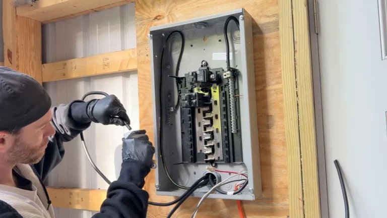
Plan out 240-volt service to areas where there are going to be heavy tools, welders, or EV chargers. A lot of powerful tools and even most EV chargers, for example, require 240 V. Strategic Upgrades include installing multiple 240V receptacles in logical areas of the first build so future equipment can go anywhere. Size breaker and feeder cable to known loads. EV charging typically utilizes a dedicated 40 to 60 A circuit. If possible, consider the simultaneous load of all tools and appliances to prevent overloads and select breaker sizes and wire gauge sizes accordingly.
Put dedicated circuits for big or constant loads instead of piggybacking lighting or general-use outlets. Put dedicated 20-amp circuits in for air compressors and heavy power tools, and separate 15-amp circuits for overhead lighting. Overhead LED fixtures, for example, are best on their own dedicated 15-amp circuit to keep lights stable when motors start. Opt for 12-gauge wire for your 20-amp circuits and use heavier wire where voltage drop could be a problem. Upgrading to 12-gauge for general-use circuits as well avoids voltage drop with your powerful hand tools and provides safety benefits.
Strategic upgrades reduce fire and shock risk and increase system reliability. Add AFCI breakers to protect against arc faults on branch circuits and surge protection at the subpanel to protect sensitive electronics and chargers from spikes. GFCI breaker or GFCI receptacles should protect all garage outlets, particularly in close proximity to potential moisture. You can punch in a standard breaker and wire the first receptacle as a GFCI-protected outlet to safeguard outlets down the line when required.
Strategic upgrades) Think controls and efficiency now. Pre-wire lighting circuits for LED fixtures and run low-voltage control conduits for future smart lighting, timers or occupancy sensors. Strategic upgrades – Leave extra conduit runs between house and garage to allow for later installation of data, control, or additional power feeders without tearing open walls. Smart conduit, proper wire sizing and isolating heavy loads on dedicated circuits will maintain the system secure and flexible.
Installation Pitfalls
Wiring a detached garage right can be a lot of little things that slip through the cracks. Below we break down common installation pitfalls and explicit steps to dodge them, along with targeted notes on panel separation, moisture protection, and final pre-power-up checks.
- Undersizing the subpanel and underestimating loads. Figure tool and equipment loads, not just lighting. A workbench with a table saw, air compressor, and heater pulls way more than a couple of lights. Design a subpanel that accommodates both your present requirements and probable future growth. If you think you will add a Level 2 EV charger at some point, install a dedicated 40 to 60 amp circuit now to oversize modestly to sidestep an expensive upgrade down the road.
- Incorrect conductor sizing for lengthy runs. Run length changes voltage drop. If you have long runs to a barn or outbuilding, select larger conductors even if the load is the same as that of a short run. Check voltage drop tables and aim for a drop of less than 3% on feeders. Use copper or aluminum and protect aluminum with anti-oxidant and terminations.
- Not separating neutral and ground in the detached subpanel. Installation Pitfalls 5) Bonding neutral and ground in a subpanel of a detached structure. The neutral needs to be isolated and a proper grounding electrode system, such as ground rods, installed at the garage. Bonding them together will create parallel neutral paths and generate stray currents on grounding conductors, raising the potential for shock and fire.
- Inadequate outlet placement and circuit planning. Identify tool locations and install sufficient outlets to keep extension cords off work surfaces. Include outlets for 120 V and 240 V tools. Install dedicated circuits on heavy-draw tools such as welders or dust collectors.
- Overlooking GFCI and AFCI protection requirements. GFCI protection in locations with moisture, dust, or metal tools is true safety, not code box-checking. Install AFCI where required to reduce arc-fault fire risk, especially in branch circuits serving the garage.
- Bad moisture and weatherproofing at entries. Seal all conduit entries and use weatherproof boxes outside. Avoid water ingress around feed-throughs, meter sockets, and junctions. Use drip loops, silicone seals, and proper gaskets to prevent water from seeping in and corroding connections.
- Installation pitfalls — loose connections, missed code checks. Double check all terminations, torque to manufacturer specs, and verify breaker sizes and conductor ampacity before energizing. Make sure permits and inspections are according to local regulations, and ensure your feeder option runs from the main house panel or a dedicated service line from the utility.
Conclusion
Wiring a detached garage in New Jersey requires defined procedures, precautions, and proper permits. Follow local code, size breakers and conductors to load, and put in a subpanel with main lug or main breaker as local rules permit. Use 6 mm² copper or 8 AWG aluminum for common runs both as depicted and choose an appropriate ground rod configuration and bonding technique in accordance with code. Include GFCI and arc-fault protection for workstations as well as living-space outlets. Avoid rookie errors such as bad connections, incorrect conduit fill, and no permit. A clean design, the appropriate materials, and a professional, licensed electrician ensure that your construction is both safe and code-compliant. Shall we continue? Book a permit check or pro consult.
Frequently Asked Questions
Do I need a permit to wire a detached garage in New Jersey?
Yes. New Jersey will require permits and inspections of new electrical work. Verify with your municipality’s building department for the exact type of permit and submission details prior to beginning work.
Can I run a feeder from my house panel to the garage?
Absolutely, if your panel has the capacity, you can run a feeder. Utilize approved cable or conduit and put a subpanel in the garage for branch circuits. Adhere to code sizing and protection guidelines.
What size wire and breaker do I need for a detached garage?
Load dependent. Common single-phase garages employ 60 to 100 A feeders with 6-3 or 3-conductor with ground in conduit. Perform a load calculation or have a licensed electrician do one to size conductors and breakers.
Does a detached garage need a separate grounding electrode system?
Yes, a detached structure with a subpanel will likely require its own grounding electrode(s), such as driven rods. Bonding and grounding must comply with the NEC and local amendments.
Can I use the house neutral for the garage subpanel?
No. The neutral and ground need to be separated at the garage subpanel. The neutral bus must be isolated. Grounds have to be bonded to the grounding electrode system.
Do branch circuits in the garage need GFCI protection?
Garage receptacles, particularly those located within 1.8 meters (6′) of workbenches, must be GFCI protected per the latest codes. GFCI saves you from being electrocuted when you’re working with wet or powered tools.
When should I hire a licensed electrician for garage wiring?
Hire a licensed electrician for service taps, feeder installation, permit work, load calculations, and anything beyond changing out an outlet. This minimizes safety hazards and guarantees code compliance.